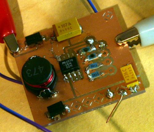
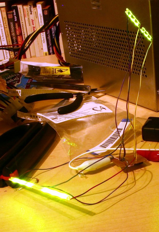
The constant-current board worked with only a few mistakes in assembly (note that some of the smoke has escaped two of the LED current-limiting resistors---I replaced them after that photo was taken)


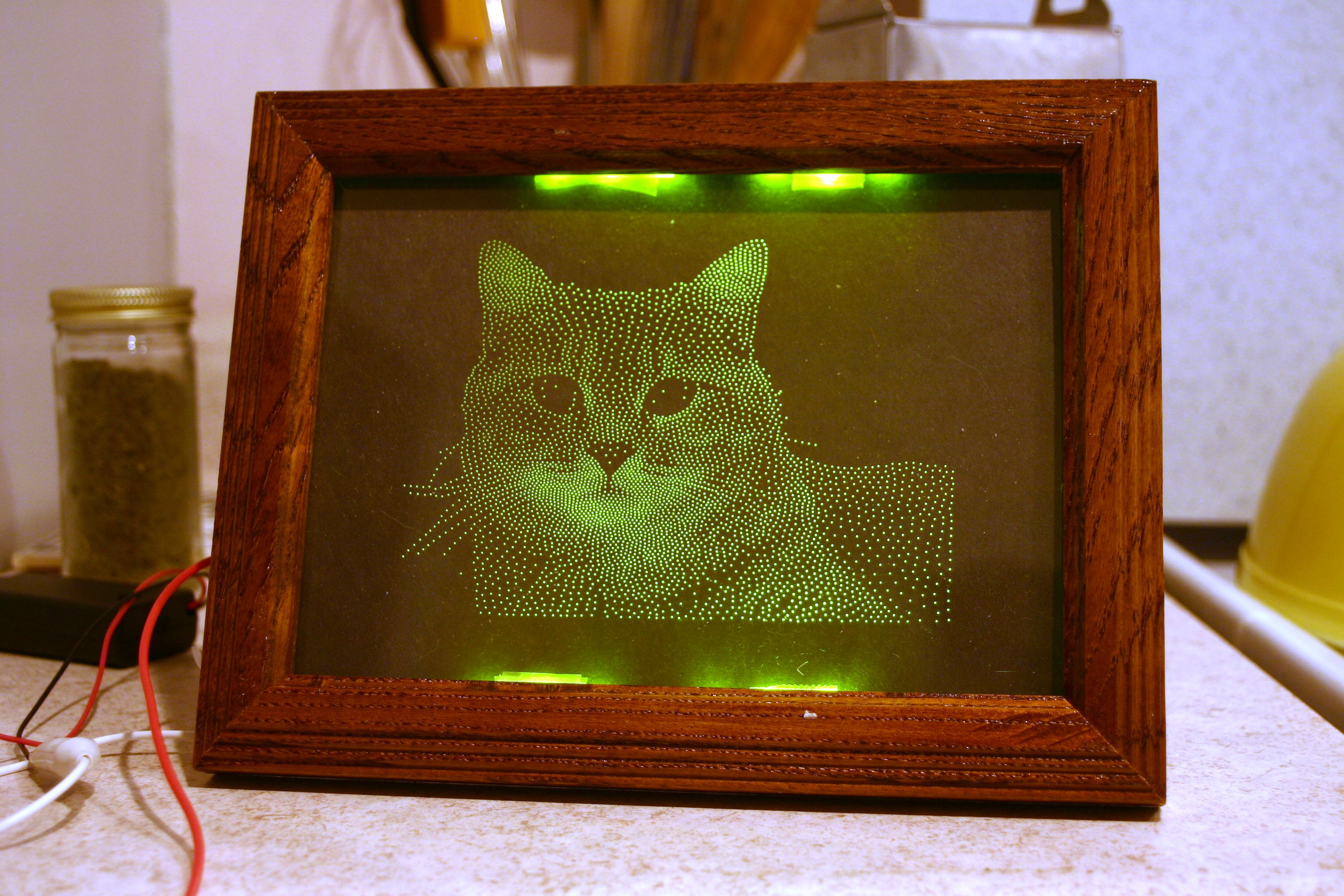
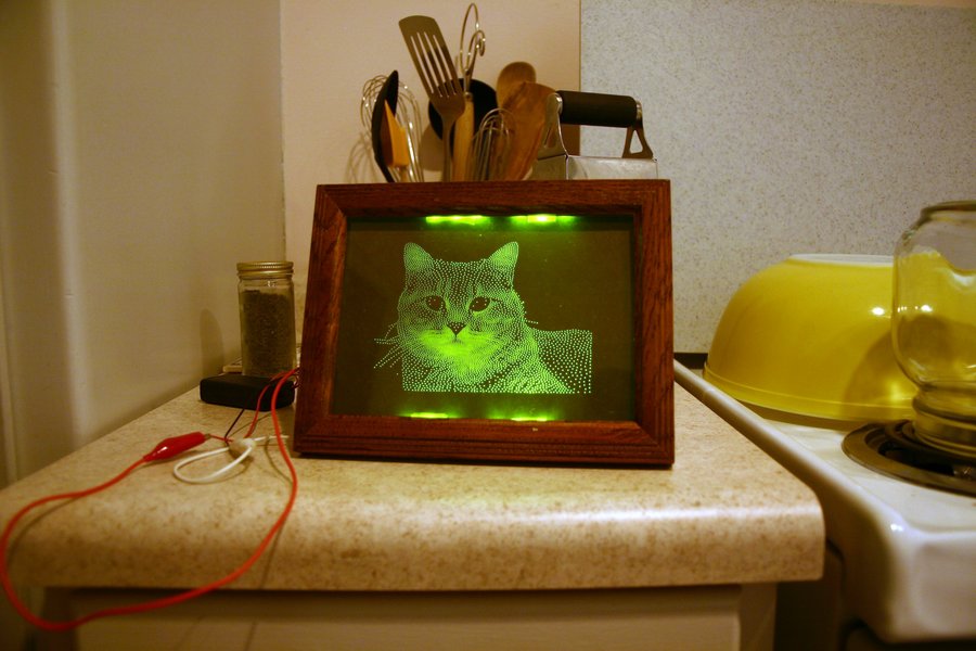
I ended up using clear tape to keep the LED sticks on the plexi. It's disappointing how visible the LEDs are at the top and bottom (partially due to the scotch tape used to hold the LED carriers to the plexiglass), and how hard the display is to see in normal artifical light (and probably completely invisible in bright daylight). On the other hand, the power of the lights is around 1/2W, and only a fraction of the light produced actually hits a cone.
The LEDs are run from a Micrel 2570 boost-mode switching power supply. I use it in a constant-current configuration, to give 20mA per string of LEDs. I've run it from a PC power supply's +5V, and from two partially-discharged AA batteries (2.5v). The brightness appeared identical in both cases, and the sense voltage measured close to 220mV both ways. The VOUT voltage measured around 7V. For the next set of LED sticks, I think I'll use 4 strands of 4 LEDs instead of 3 LEDs per strand, getting me a third more light.
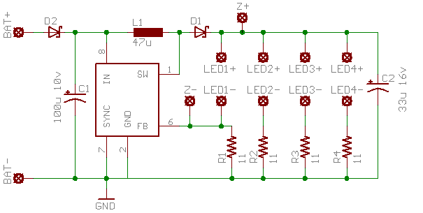
The confusingly-labeled Z+ and Z- pads have a 12.0V 1W zener wired between them, with the cathode at Z+. Without this diode, the board could fail catastrophically if the string of LEDs used for current-limiting becomes disconnected: FB is pulled down to GND through R1, and the MIC2570 goes into continuous boost until it either reaches the current limit or the voltage rating of the output capacitor (16V) is exceeded. Tantalum capacitor datasheets all warn that when the voltage rating is exceeded, the capacitor may explode! Needless to say, I didn't want to test this. In normal operation, the Z diode doesn't conduct.
The 12.0V value was chosen to be above the maximum drop across 4 LEDs (4 * Vf_led <= 4 * 2.8V = 11.2V) and below the voltage rating of the output capacitor (16V). Plus, a 12.0V zener was available.
The input diode will probably be removed from the next iteration of the board. While it's nice to be protected against the wrong input polarity (I recently made a polarity mistake and I'm lucky I didn't fry my laptop's parallel port in the process) the ~.4V drop means an almost 15% decrease in efficiency when powered from 2 AA cells at 3V
| Name | Mouser item# | Qty |
|---|---|---|
| U1 | 803-MIC2570-2BM | 1 |
| C1 | 8581-TPSD107M010R0100 | 1 |
| L1 | 8673-P0751.473T | 1 |
| R1..R4 | 8660-RK73H2BLTD11R0F | 4 |
| C2 | 8581-TPSC336M016R0300 | 1 |
| LEDs | 8512-QTLP652C4 | 12 |
| 2xAA Battery case | 812BH325/CS | 1 |
| D1, D2 | 8512-SS14 | 1 |
(Not show in bill of materials: zener diode Z1, circuit boards, batteries, picture frame, plexiglass)
Files currently attached to this page:
| img_9012-medium.jpg | 140.5kB |
| img_9012-small.jpg | 37.0kB |
| img_9012.jpg | 171.4kB |
| img_9015-medium.jpg | 117.9kB |
| img_9015-small.jpg | 20.0kB |
| img_9015.jpg | 263.4kB |
| img_9019-medium.jpg | 83.5kB |
| img_9019-small.jpg | 45.2kB |
| img_9019.jpg | 829.5kB |
| img_9020-medium.jpg | 114.1kB |
| img_9020-small.jpg | 17.1kB |
| img_9020.jpg | 1.0MB |
| regulator-brd.png | 9.3kB |
| regulator-sch.png | 6.0kB |
Entry first conceived on 23 February 2005, 3:03 UTC, last modified on 15 January 2012, 3:46 UTC
Website Copyright © 2004-2024 Jeff Epler