Towards fast I/O in Arduino for AVRs
So I've been working on something. I've only looked at assembler output so far, but it looks right and promising.
Basically, I'd like to let you name I/O pins via typedef, then efficiently read and write the pins. And I'd like to make Arduino's digitalWrite just as efficient when the pin argument is a constant.
All instruction counts are in Debian Wheezy's avr-gcc version 4.7.2 with -mmcu=atmega328p -Os specified on the commandline.
// You can declare ports (they use zero RAM)
typedef IOPIN<PORT_B, 0> iob0;
typedef IOPIN<PORT_B, 1> iob1;
typedef OCPIN<PORT_B, 1, true> ocb1; // emulate an open collector port

// .. and use them efficiently (instruction counts never include ret)
int en() { iob0::output(); }                // 1 instruction
int fn() { iob0::toggle(); }                // 1 instruction
int gn() { ocb1::set(); }                   // 2 instructions
int hn() { ocb1::clear(); }                 // 2 instructions
int jn(bool b) { iob0::write(b); }          // 5 instructions
int kn() { iob0::write(1); }                // 1 instruction

// you can use fastDigitalWrite just like digitalWrite (but faster and inline)
int c(int i) { fastDigitalWrite(1, i); }    // 5 instructions
int d() { fastDigitalWrite(1, 1); }         // 1 instruction

// these have a variable port so they still turn into calls to digitalWrite
int a(int i, int j) { fastDigitalWrite(i, j); }
int b(int i) { fastDigitalWrite(i, 1); }
Files currently attached to this page:
| fast_io_prototype.cpp | 6.2kB |
WWVB clock progress
Chris was kind enough to pass along to me a commercial WWVB receiver. This module was a bit of a pain to develop for, because most of the time the interference from a nearby laptop computer is enough to seriously compromise reception, and almost all of the time having a USB cable running from the microcontroller to the laptop will kill reception outright.
Towards my GPS LED Light Clock
A few years ago, I made a CCFL light clock using an Arduino with a custom shield containing a transformer (to get a reliable 60Hz timebase) and a triac (for solid-state switching of the lamp). By having a simple 7-day alarm calendar (set at compile time), the clock seldom requires interaction except for the reading lamp function.
However, the design has two main problems:
Arduino Random Number Generator
Inspired by other designs I've seen online, most directly Rob Seward's design, I decided to build my own random number generator based Will Ware's "avalanche noise in a reverse-biased PN junction" (try this mirror of Will Ware's page). Also important is turbid which introduced me to the concept of hash saturation and the math behind it.
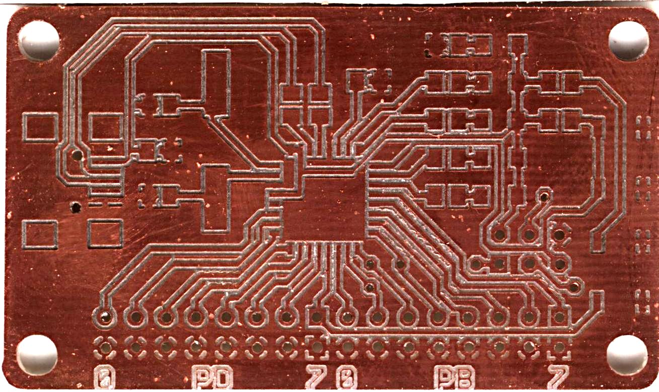
at90usb162 single-sided board
I got an e-mail request for this board. You may use this eagle (4.x) library, schematic, and board under the GNU GPL version 2 or later, or CC-BY-SA.
Autoreprogram for DFU devices
It's a bit of an annoyance to first have to press a combination of two buttons on my at90usb162 board, then run a sequence of 4 dfu-programmer commands.
Thanks to the magic of the freedesktop 'hal', though, I've written a program that waits for the dfu device to appear. It then erases and flashes the device, finally restarting into the newly uploaded firmware.
Modify the program to name your .hex file (and avr partnumber if it's different), then leave it running in the background. It's still necessary to tickle the RESET and HWB buttons in the proper way after rebuilding your firmware, but it does shorten the process.
Files currently attached to this page:
| autoprogram.py | 1.5kB |
at90usb162 gotcha: PC0 vs XTAL2
I spent a very long time trying to diagnose a board-level problem in my current project, an (almost all) surface-mount board based on the at90usb162. The board would reliably program over USB (which is very cool) but the programs I was running to blink the onboard LEDs would lock up. When I discovered that touching the body of the crystal would give me a slow-running program, I was convinced that I had bad placement of the crystal, or incorrect capacitors, or the like.

Finally after much head-scratching, I decided to restrict the DDRC to just some of the pins on the port -- before I'd set DDRC = 0xff. Well, it turns out that PC0 is a shared function with XTAL2. Apparently turning on bit 0 of DDRC turns this pin into an output, and makes the crystal stop running. Touching the crystal's can coupled 60Hz ambient noise into it, which was amplified enough to be treated like the external clock (I had suspected that the LEDs were blinking much slower than they should have been, but wasn't entirely sure)
Now I'm tempted to declare this board "working". whee!
Update, 2009-03-19: This board has been incorporated in a project. Yay!
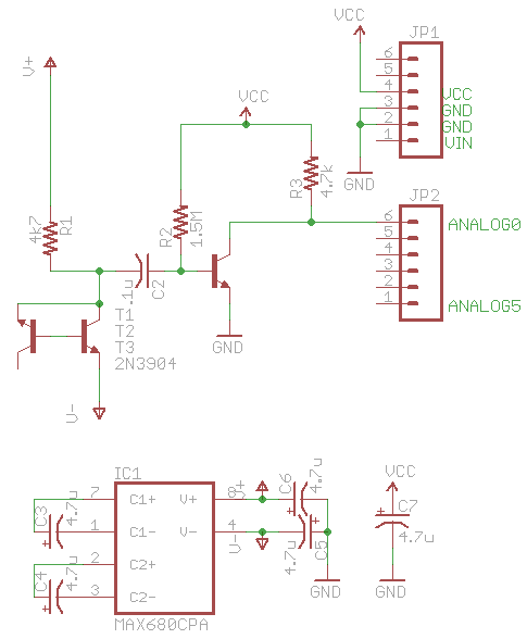
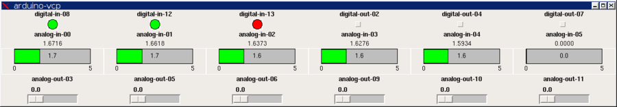
Improved Analog & Digital Interface with Arduino
Building on my earlier work, I've now improved the interface between HAL and the Arduino board to have:

- 6 10-bit analog inputs
- 6 8-bit PWM "analog" outputs
- 6 digital inputs/outputs (partition chosen when component is loaded)
- GPL license statement in source files
All older entries
Website Copyright © 2004-2024 Jeff Epler