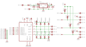
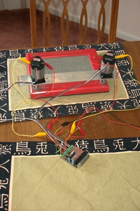
An L298 dual full-bridge is driven by EMC: the direction of each axis is set by the two INPUT bits, and the speed is set by a PWM signal on the ENABLE bit.
Feedback from the motors comes in the form of two TTL signals in quadrature encoding. These inputs are read and decoded by EMC.
The board is assembled and tested, and the emc2 configuration is done except for the PID tuning and backlash compensation. Compared to steppers, which achieved 2 inches per second, the servo motors achieve 3IPS in "Y" and 4IPS in "X" when running on a +12V supply (I've had to decrease this a bit to improve reliability, but it's still faster than the steppers). The motors have a nominal voltage of 30V, and the L298 can handle up to 46V, but with my board design it's not possible to use supply voltages above 12V due to the heat dissipated in the +5V regulator.
In my opinion, the fact that emc2 could be easily adapted to this newly-created hardware without writing any "C" code speaks to the strength of its hardware abstraction layer. (In fact, I did write a tiny amount of code, but only because I was unware of a HAL component called 'or2')
I haven't gotten around to tuning or taking any good photos. Maybe soon.
Update: The Eagle schematic and layout are now available.
Entry first conceived on 14 March 2006, 14:50 UTC, last modified on 15 January 2012, 3:46 UTC
Website Copyright © 2004-2024 Jeff Epler


