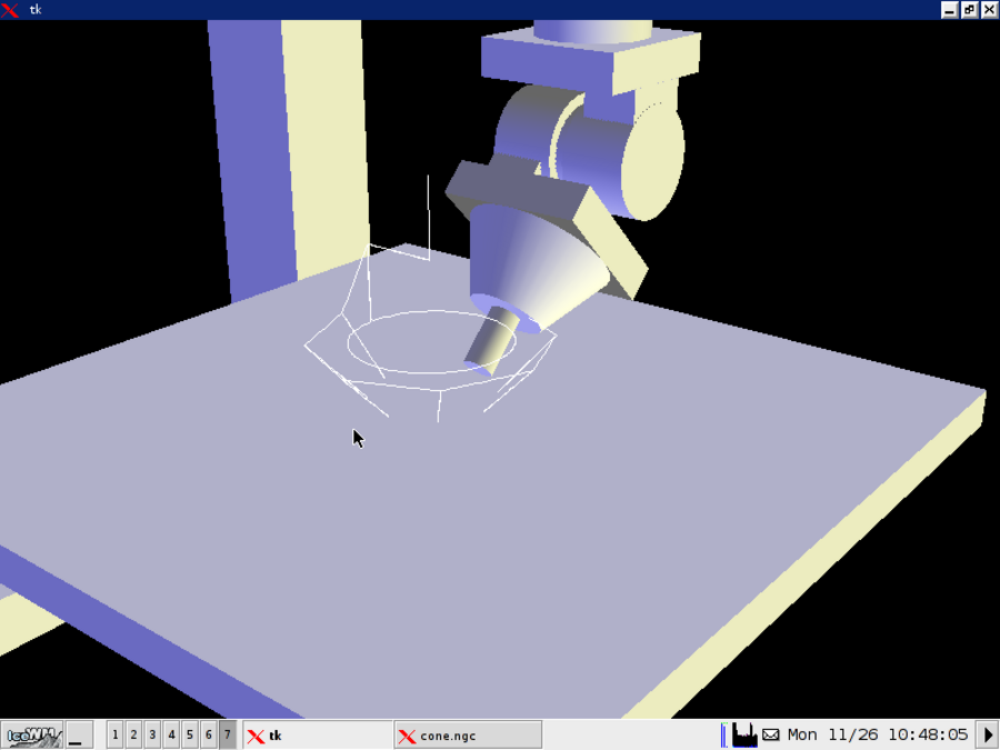
The simulated machine has 5 axes: XYZBC, with the tool at the end of the stacked rotary BC axes.
The kinematics module for the machine performs tool length compensation for any tool orientation.
One hard problem is correctly enforcing machine constraints for moves of the B and C axes and tool compensation is turned on. Imagine there's a tool 100mm long. To hold the tool tip in a constant position, rotating B or C may move the X, Y and/or Z joints substantially. EMC doesn't have an infrastructure that allows the task portion of the planner (where constraints are enforced) to know about this detail of the machine kinematics. It's too soon to tell whether this will lead to severe or mild constraint violations in real-world situations.
Chris and I have chatted about adding some features that would make it easier for those hand-writing code for 5-axis machining. Basically, this consists of making the UVW axes move in the plane defined by the BC orientation. The hypothetical new gcodes G17.1, G18.1, G19.1 would select planes in the UVW coordinate systems, making everything that uses planes (canned cycles, arcs, tool shape and radius offsets) work in those coordinate systems.
This would mean that you select a plane to mill in by setting XYZBC, then move in that plane by UVW moves. Facing is as simple as some linear moves in UV, and canned cycles would "just work" for drilling.
And now, the promised video:
(originally posted on the AXIS blog)
Entry first conceived on 26 November 2007, 16:30 UTC, last modified on 15 January 2012, 3:46 UTC
Website Copyright © 2004-2024 Jeff Epler