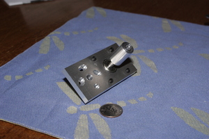
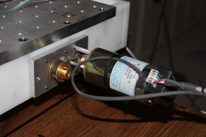
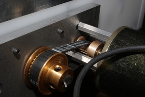
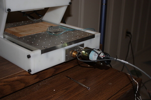
With copious help from Chris, I designed a pulley reduction system with a 12:28 ratio that would connect to the machine using the existing holes for the NEMA 17 steppers and attach to the screws with a coupling similar to the original couplings.
Chris also did all the CNCing for these parts, of course.
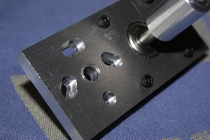
The motor is mounted using hex standoffs and hex socket cap screws, which are counterbored on the far side so that the heads do not stick out of the plate. One is a simple hole; three are arc slots. The belt is tensioned by pushing firmly on one of the pivoting standoffs before tightening the screws. (The calculated pulley distance of 1.385" based on tooth counts turns out to be pretty close to right)
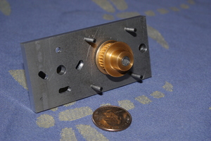
On the other side of the plate from the motor, there is a ball bearing with a dowel pin pressed into it. The dowel pin, in turn, is pressed into a solid coupling which is attached to the leadscrew with a setscrew. On the other end, the dowel pin has two flats for the pulley.
The most finicky part of the construction was probably the pulley for the motor: I could not find a pulley bored to match the .1562 motor shaft. Chris rose to the occasion by reaming a 1/8 pulley out to match.
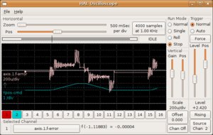
Today, with the finishing touches put on the parts for the first axis, I finally hooked the motor up to emc (using a mesa 5i20 with 7i30 servo driver daughtercard; by the way, the 794194-1 receptacle that mates with the 7i30 is not difficult to populate using a basic crimp tool) and tuned it a bit. Things appear promising---when in motion, it's hard to do more than slow it a bit it by pressing against the motion. And even though I'm new to PID tuning I quickly got some fairly decent results.
Next come the other two axes and lots more tuning and testing.
Entry first conceived on 22 June 2009, 1:41 UTC, last modified on 15 January 2012, 3:46 UTC
Website Copyright © 2004-2024 Jeff Epler
