Because emc2's encoder module poops out somewhere around 20 microsecond polling intervals, an external divider is the only way to get accurate feedback from a fast servo motor with a high-resolution encoder. Division by 16 lets the PC see a 25kHz quadrature signal instead of a 400kHz one. For Chris's lathe retrofit, the target speed is actually around 125kHz (1250 mm/min, 1mm/rev leadscrew, 3:1 pulley, 500 line/rev encoder), but to keep it from being too easy, he's going to do 3 such decoders on a single 16MHz atmega.
Many people seem to hit on the idea of using an up/down counter to process a quadrature input. Chris and I managed to convince a couple of bright guys on the #emc channel that this would work to create a quadrature divider circuit. Well, it doesn't.
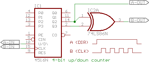
Here's how the circuit is supposed to work: the quadrature signal is treated as a step+direction signal. On the falling edge of "B IN", one count in the direction indicated by "A IN" is taken. When the waveform is moving in one direction, "B IN" will consistently be high when "A IN" falls; when it's moving in the other direction, it will be low.
When the encoder is consistently rotating one direction, this circuit behaves as described above. But what happens when the encoder reverses, or switches back and forth across a single transition? In the waveform shown in the image, DIR (A IN) is high, while CLK (B IN) has multiple falling edges. As a result, the output will erroneously count up.
These kinds of waveforms happen in several cases: First, when the encoder changes direction. Second, when there is enough noise on B IN that the counter chip sees several falling edges. You'll notice the second cause right away, and maybe you'll be able to fix it with an RC filter on the B input. The second cause is more subtle, but eventually it will bite you, especially if you're using an encoder for servo feedback, not just to read clicks on a dial for a user interface.
What's the real solution? Something with state. John Kasunich has suggested an approach with a 256-element LUT (for divide-by-16) that seems to be able to poll every dozen AVR cycles or so.
Coming soon: Now available: quad-tiny13, a microcontroller-based (attiny13)
quadrature divider which samples at 1MHz+ and can divide by 4, 8, or 16
(selectable at compile-time)
Also available: quad-mega8, a
microcontroller-based (atmega8) quadrature divider which samples 3 channels at
400kHz+ and can divide by 4, 8, or 16 (selectable at compile-time)
Entry first conceived on 31 May 2006, 16:57 UTC, last modified on 15 January 2012, 3:46 UTC
Website Copyright © 2004-2024 Jeff Epler