Like the 400kHz triple divider, this program uses a state table generated by "mkstate.py", and is GPL software.
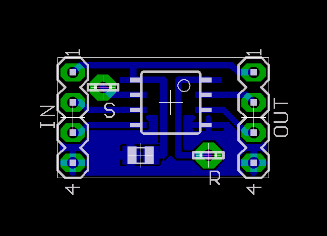
For real-world use, external pull-ups should probably be added to the board's input side, according to the directions of the encoder manufacturer.
Update, 6/2014: Some notes from Paul M:
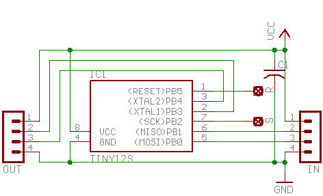
I noticed in the source you have PORTB and PINB used at the bottom of quad-tiny13.S where you're reading the pins, operating the state table and outputting. I think these should be PORT & PIN, which is to say the converted addresses. I had to change these (using gcc-avr, avrdude in linux etc) for it to work. Also the quick out statement works fine. Nice job lining up the bits, that's pretty cool!
Files currently attached to this page:
Entry first conceived on 3 June 2006, 15:25 UTC, last modified on 11 June 2014, 0:07 UTC
Website Copyright © 2004-2024 Jeff Epler