« Post-Fest Post | Newest entries | Creating a Quadrature Divider: What Won't Work »
I didn't originally include the eagle-format schematic and board for this project. Well, here it is. I suggest revising this board to use separate Vdrive and Vcc power inputs if Vdrive is above 12V. Another approach might be to switch to a TO-220 regulator—as I noted in the other entry, the TO-92 gets quite hot if you try to run it on 24V. My first guess is that the logic draws up to 100mA, depending on the encoders. It would also be a good idea to ensure the capacitors are appropriate to the task.
Files currently attached to this page:
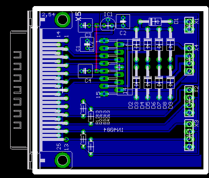
| l298-servo-brd-small.png | 61.7kB |
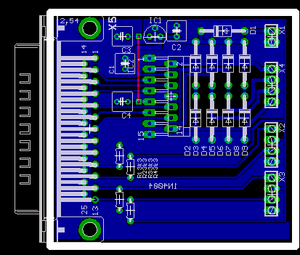
| l298-servo-brd.png | 14.0kB |
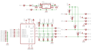
| l298-servo-sch-small.png | 25.9kB |
| l298-servo-sch.png | 17.5kB |
| l298-servo.brd | 19.2kB |
| l298-servo.sch | 96.3kB |
Entry first conceived on 22 May 2006, 13:13 UTC, last modified on 19 March 2009, 17:38 UTC

