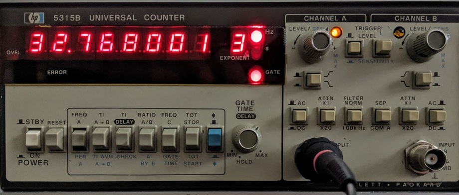
The DS3231 and PCF8523 real time clocks (RTCs) can both be calibrated by writing various register values. To follow the calibration procedures you'll need a frequency counter you trust, with at least 6 digits to calibrate the PCF8523 and 7 digits to calibrate the DS3231. (It also has to operate at the comparatively low frequency of 32.768kHz; a common inexpensive 8-digit frequency counter such as the "SANJIAN STUDIO" has a minimum of 100kHz so it's not usable for this purpose) I use an old HP 5315B universal counter that has been calibrated against GPS time.
The DS3231 is the one that can be more precisely calibrated, and it is also the easiest. Simply place a pull-up resistor on the "32kHz" pin and measure the frequency. Set the value of the 8 bit signed register 0x10 higher to decrease the frequency and lower to increase it.
Because the adjustment is accompilshed by changing the capacitance of the oscillator circuit, the new frequency is made directly visible on the frequency counter after forcing a temperature conversion, so you can check the result of the adjustment on the frequency counter right away.
With the latest version of adafruit_ds3231, you can access the adjustment using the calibration property. I was able to calibrate the oscillation frequency at room temperature to 32768.001Hz, as shown above. The last digit drifts up and down by about +-2 milliHz in ambient conditions, and also changes depending on the orientation of the RTC board. Yes, your crystal oscillator is also a very bad accelerometer or orientation sensor
The PCF8523's calibration is more complicated. Again, you start by connecting a pull-up resistor, this time on the pin marked "INT", which will now have a nominally 32.768kHz square wave for measurement. First, you have a choice of two capacitance values. Selecting the higher capacitance value lowers the frequency by around 2Hz in the two devices I had, and in both cases it made the crystal's base frequency much closer to 32768Hz. Second, you have a choice of two adjustment schedules, "every 2 hours" and "every minute". Finally, you have a choice of the number of ticks to add or remove each time an adjustment is made. The adjustment step is around 4ppm, but the specific value is different depending on the adjustment schedule. The datasheet figure 18 shows how to go from a measured frequency value to a frequency offset value; potentially, you can choose which of 4 scenarios (capacitance and adjustment schedule) lets you get closest to the right frequency. Since only the high-capacitance setting affects the frequency visible on the INT pin, for the ultimate test of calibration you will have to resort to long term measurement of drift to evaluate the result. The latest adafruit_pcf8523 library lets you access the calibration, calibration_schedule_per_minute, and high_capacitance properties to set the best timekeeping possible.
Ultimately, because the DS3231 has a TCXO and because the calibration steps are about 40x finer, it will give the best timekeeping. However, for either device in a constant indoor environment, you should be able to get the calibration to a level of a minute a year or better. Based on a sample of 2 PCF8523s, even if you do not have a frequency meter to do full calibration, you should see much better accuracy just by setting CAP_SEL=1.
The following Python3 program implements the PCF8523 offset calibration workflow, choosing the best alternative given the two directly measured frequencies.
Measure the frequency with CAP_SEL=1 (f_lo) and CAP_SEL=0 (f_hi), then insert the measured frequency values in the correction_full() call and run the script:
Entry first conceived on 16 July 2020, 18:22 UTC, last modified on 23 June 2021, 13:19 UTC
Website Copyright © 2004-2024 Jeff Epler