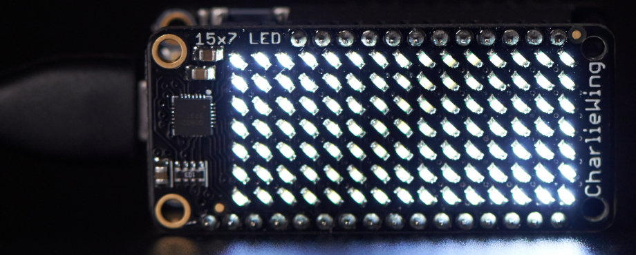
Adafruit makes these neat "CharlieWing" displays that allow you to control a 15x7 LED matrix using the I2C bus. I2C uses two signal wires (called SDA and SCL, for Serial DAta and Serial CLock), and can connect multiple devices as long as they have different addresses.
I noticed that the bigger brother of this device, with a whopping 144 LEDs, could be configured for 4 different I2C addresses, while this one could only be configured for 2.
Or could it?
Both are based on a driver chip called the IS31FL3731. The 4 address choices come from connecting the "AD" address-selection pin in one of 4 ways:
- Connected to or pulled down to GND (0x74)
- Connected to SDA (0x75)
- Connected to SCL (0x76)
- Connected to VCC (0x77)
Here's how I wired the 0x75 address up:
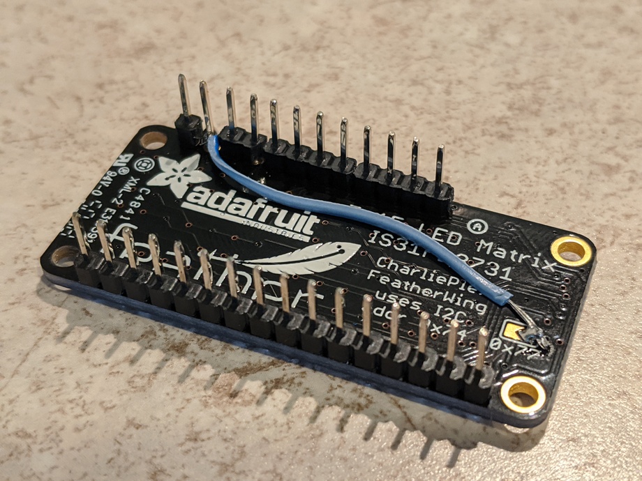
When soldering the headers, break off a 1x1 header for SDA, or SDA and SCL. Sand the black plastic of the 1x1 headers down a little so there is a gap between them and their neighbors. Solder the headers in as normal. Then, you have to remove the plastic from the address pin. You can do this by either nibbling away at it with flush cutters, or just pulling on it firmly with with needle nose pliers. Either way, there is some risk that you will damage the solder traces and make the board unusable, so be careful. Happily, I did 2/2 without any board damage.
Now, prepare a bodge wire that will go from the "right" half of the address select jumper to the base of the pin you just exposed. I used a piece of stranded wire salvaged from an old HDD ribbon cable, but any fine wire will do. Wrap the wire around the SDA or SCL pin, and put a blob of solder on it, making sure it is all below the level of the plastic insulators. Then, solder the other end of the wire down on the right side of the solder jumper (above the "77" of "0x77", being careful not to create a bridge between the left and right sides.
Hook the board up to a feather and run an I2C scan. Now it should appear at address 0x75 or 0x76. By following this procedure twice (once with SDA and once with STL) you will have 4 CharlieWings that can be used together with one Feather!
Any method of hooking up the SDA or SCL pin will also work. I liked this one
because it keeps the module self-contained. But if you will install the
featherwing above the prototyping area of a Quad FeatherWing, for instance, you
can run the address-selection wire from the solder jumper to the spot where
SDA/SCL are exposed in the prototyping area. Of course, you will have to
desolder that wire if you want to move the display to a different location.
Entry first conceived on 18 July 2020, 13:21 UTC, last modified on 18 July 2020, 14:05 UTC
Website Copyright © 2004-2024 Jeff Epler