Pi Zero W USB Proxy
I'm not sure exactly what to call it, but here's a little something I set up this weekend.
On my Linux desktop, I have occasional problems where being stopped at the debugger prompt for a plugged-in USB device hoses the whole computer. The problem waxes and wanes but on a particularly frustrating day I decided that maybe a Pi was the answer to the problem.
Using screen I can access the USB-serial devices on the pi, and using sshfs I can access the files. If the whole pi freezes, I can just reboot it with essentially no harm done.
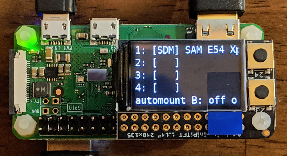
I selected a Pi Zero W with a Zero4U hub and Adafruit MiniPiTFT 1.14" attached. To a base raspbian lite system I added some software, including tio, udiskie, screen, and Adafruit Blinka; enabled ssh access and disk mounting by the pi user, and set up GNU screen and my custom script for the LCD which is (confusingly) also called screen.
The screen shows information about each of the 4 USB connectors. In brackets "S" is shown if there is a serial device; "D" is shown if there's a partitioned disk, "d" if there's an unpartitioned disk; and "M" is shown if it is mounted. After that, the device name is shown.
Automount can be toggled with the B button (silk screen 23) and any non-mounted disks can be mounted with the A button (silk screen 24)
So far I've only used it lightly, but if it prevents a single crash of my desktop, it will be worth it.
This isn't a detailed guide so a lot of the setup is omitted. However, here are the scripts that are the essential parts:
Some notes on the Si5351a
Si5351 "XA" can be driven by a clock signal (25/27 MHz, 1Vpp)
    source: [2] p23, figure 14

Internet commenters report success driving it with a much wider frequency range
as well as successfully exceeding the specified PLL range.  Inputs from 3MHz to
146MHz and PLL frequencies from 168 to 1168MHz were tested.
    source: [1]

intermediate PLL frequency:
    600 to 900 MHz [3] p2
    divider range 15 + 0/1048575 .. 90
    "integer divide" FBA_INT flag is for _EVEN_ integers [3] p4

multisynth:
    valid dividiers are 4, 6, 8, 8 + 1/1048575 ... 2048
    "integer divide" FBA_INT flag is for _EVEN_ integers [3] p6
[1]: http://www.simonsdialogs.com/2018/11/si5351a-any-frequency-cmos-clock-generator-and-vco-specifications-myths-and-truth/
[2]: https://www.silabs.com/documents/public/data-sheets/Si5351-B.pdf (rev 1.3)
[3]: https://www.silabs.com/documents/public/application-notes/AN619.pdf Manually Generating an Si5351 Register Map rev 0.8
Si5351 Frequency Planner in Python
The Si5351 and related clock generators are very flexible, but they are a bit cumbersome to "program".
The basic design of the Si5351 is that an incoming frequency is first multiplied to create a high internal frequency (nominally in the range from 600MHz to 900MHz), then divided to create an output frequency. The multipliers and dividers have restrictions on their ranges, there are just 2 PLLs but 3 output clocks, and certain types of configurations (e.g., "divisor is an integer multiple of 2") are said to give lower jitter outputs than others.
The datasheet advising users on how to create their own register values is very complicated and some of the parts resist comprehension even after multiple readings. Thie chip maker Silicon Labs provides a graphical closed source Windows program for generating register maps, though some internet commenters regard it as buggy.
This program represents my own effort to create a frequency planner. It neglects some datasheet rules, mostly related to output frequencies above 50MHz or so. It tries to
- Favor lower-jitter configurations where possible
- Favor making the first-listed frequency as accurate as possible
- Try each combination of ways to allocate output clocks to the PLLs
- Obey the datasheet restrictions as I've understood them
- Do all arithmetic as infinite precision arithmetic, not floating point
- Implement the divisor rules for extremely fast clocks
- Implement the divisor rules for higher numbered outputs on 20QFN packages
For exact input clocks such as 25MHz, it is surprisingly hard to find a "plausible" frequency that is inexact, and even harder to find a "plausible" frequency that is less exact than your reference clock. I didn't actually find a case where the error is not much smaller than the frequency stability of any reference I'd plausibly have access to.
(Of course, if you measure your reference clock as 25MHz + 13.37Hz and plug that in as the --input-freq then almost everything is related to that clock inexactly, so the fact that the clocks will still be really, really close to the requested value is very nice.)
It does not directly create a register map, but the values shown are easy enough to convert to the form used in the CircuitPython adafruit_si5151 library. Sadly, as CircuitPython does not support the fractions module, it's not currently feasible to run this code on a CircuitPython board directly controlling the si5351 chip.
Example:
Generate 315M/88 (NTSC colorburst), 4.43361875M (PAL colour carrier), 25.8048M (UART clock) all exactly from a 25MHz reference clock or crystal. However, the PAL colour carrier will have more jitter since it uses a fractional divisor:
$ ./party.py 315M/88 4.43361875M 25.8048M
Input frequency: 25000000 (25000000.0)
Frequency plan score: 10.38

PLL A:
Frequency plan type: Fractional multiplier, double integer divisor (1)
Multiplier = 126/5 (25.2)
Intermediate frequency = 630000000 (630000000.0)

Desired output frequency: 39375000/11 (3579545.4545454546)
Divider = 176 (176.0)
Exact
r_divider = 0 (/ 1)


PLL B:
Frequency plan type: Fractional multiplier, fractional divisor (5)
Multiplier = 12059443/500000 (24.118886)
Intermediate frequency = 602972150 (602972150.0)

Desired output frequency: 17734475/4 (4433618.75)
Divider = 136 (136.0)
Exact
r_divider = 0 (/ 1)

Desired output frequency: 25804800 (25804800.0)
Divider = 12059443/516096 (23.366666279141864)
Exact
r_divider = 0 (/ 1)
Generate pi MHz from a 25MHz reference clock or crystal (error: 27.8 nano Hz)
$ ./party.py 3.1415926535898M
Input frequency: 25000000 (25000000.0)
Frequency plan score: 1.00

PLL A:
Frequency plan type: Fractional multiplier, fractional divisor (5)
Multiplier = 24 (24.0)
Intermediate frequency = 600000000 (600000000.0)

Desired output frequency: 15707963267949/5000000 (3141592.6535898)
Divider = 40306053/211042 (190.98593171027568)
Actual output frequency: 42208400000000/13435351 (3141592.653589772)
Relative Error: -8.83757e-15
Absolute Error: 2.78e-08Hz
r_divider = 0 (/ 1)
The source is available in a github gist:
Quad CharliePlex FeatherWing hack
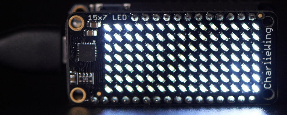
Adafruit makes these neat "CharlieWing" displays that allow you to control a 15x7 LED matrix using the I2C bus. I2C uses two signal wires (called SDA and SCL, for Serial DAta and Serial CLock), and can connect multiple devices as long as they have different addresses.
I noticed that the bigger brother of this device, with a whopping 144 LEDs, could be configured for 4 different I2C addresses, while this one could only be configured for 2.
Or could it?
Calibrating the DS3231 and PCF8523 RTCs
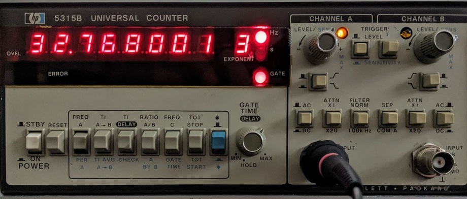
The DS3231 and PCF8523 real time clocks (RTCs) can both be calibrated by writing various register values. To follow the calibration procedures you'll need a frequency counter you trust, with at least 6 digits to calibrate the PCF8523 and 7 digits to calibrate the DS3231. (It also has to operate at the comparatively low frequency of 32.768kHz; a common inexpensive 8-digit frequency counter such as the "SANJIAN STUDIO" has a minimum of 100kHz so it's not usable for this purpose) I use an old HP 5315B universal counter that has been calibrated against GPS time.
Helpful Scripts for CircuitPython & Real Time Clocks (RTCs)
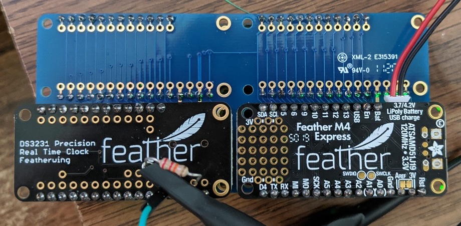
I have used two different RTCs in the Feather form factor. One has the PCF8523, and the other has the DS3231. The former has an SD card slot while the latter has higher precision including a temperature-compensated crystal oscillator.
Precision vs Accuracy: A Clock
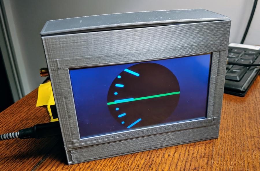
I was inspired by this watch face design (I think that's the original version) and by the arrival of a "OCXO", a very reliable time keeping circuit, to finally make an electronic clock.
Accuracy: Between hardware and software tuning, the OCXO keeps time with an accuracy of possibly better than 100 microseconds per day (loses or gains well less than a half second per year) (Yes, I'm deliberately ignoring a lot about crystal aging here!)
Precision: The time displayed is to the nearest minute, and the touchscreen setting mechanism is (deliberately?) poor, making it hard to set the time closer than +- 2 minutes or so. Oh, and it takes a good fraction of a second to update the screen anytime it changes. (The best way to set it seems to be to wait until a few seconds before 6AM/6PM and plug it in, since it boots with that time showing)
The clock consists of: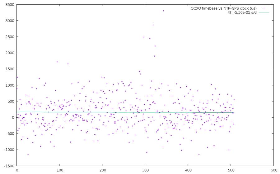
- A PyBoard running micropython
- A touchscreen LCD and controller
- A 10MHz OCXO frequency reference
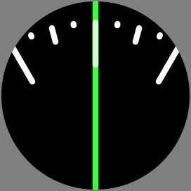
The dial as an animation (1 revolution = 12 hours)
Time to finish that languishing clock project!
A leap second has been announced at the end of June 2012.
Side track: wwvb links
Soldering "helping hands" made with Loc-Line coolant hose
Arduino Random Number Generator
Two-element capacitative touch sensor
Bah, it's garbage
1MHz+ Quadrature Divider for attiny13
400kHz Triple quadrature divider for atmega8 and quadrature state table generator
Creating a Quadrature Divider: What Won't Work
All older entries
Website Copyright © 2004-2024 Jeff Epler